Tutorial 1: Decorrugating a grid
If you encounter errors during processing, then view the System Log File – File|View System Log File.
Run MicroLevel by double-clicking the desktop icon. Take a moment to familiarise yourself with the main window. You will notice that almost all the sub-menus off the menu bar are not enabled. These will be enabled once the Working Directory and Aliases and Parameters are set.
- Set the Working Directory – File|Set Working Directory. Navigate to the "decorrugate" sub-directory of the "demo_data" folder and click the Select Folder button. A message will be displayed in the Messages showing the Working Directory set. You should be in the "decorrugate" directory. The Utilities menu items are now enabled.
- Set Aliases and Parameters – Set Aliases And Parameters|Set Aliases and Parameters. There are three ways to set the aliases and parameters: you can type directly into the text boxes (tedious and prone to typos); you can select files and folders using OpenFileDialogs launched by clicking the folder icons to the right of the text boxes (slightly less tedious); or you can load the aliases and parameters from a program control (.pc) file. We are going to use a control file. Click the Load From File button, then select the "decorr_p1528_mag.pc" control file. Familiarise yourself with the decorrugate aliases and parameters. For info on the use of a control file, see Using The Control File. To see what all the fields in a control file mean - see Sample Control File. Click the Save And Close button to exit the Set Aliases And Parameters window. The magnetic grid for project 1528 will display in the left panel window.
- Decorrugate the grid – Decorrugate|Decorrugate. This will launch the Decorrugate process using the current alias and parameter settings. Wait for the process to finish. The decorrugated grid will appear in the right panel, as shown in the figure below. You can resize the window if you like, or zoom and pan in any of the image panels. The mouse scroll wheel will zoom about the current cursor position, and the left mouse button can be use to pan using "click and drag". Click the Reset button to re-centre the images in the panels. The decorrugation is typically repeated using different parameters until a good result is obtained. See the section Tips And Tricks for hints on how to go about decorrugation.
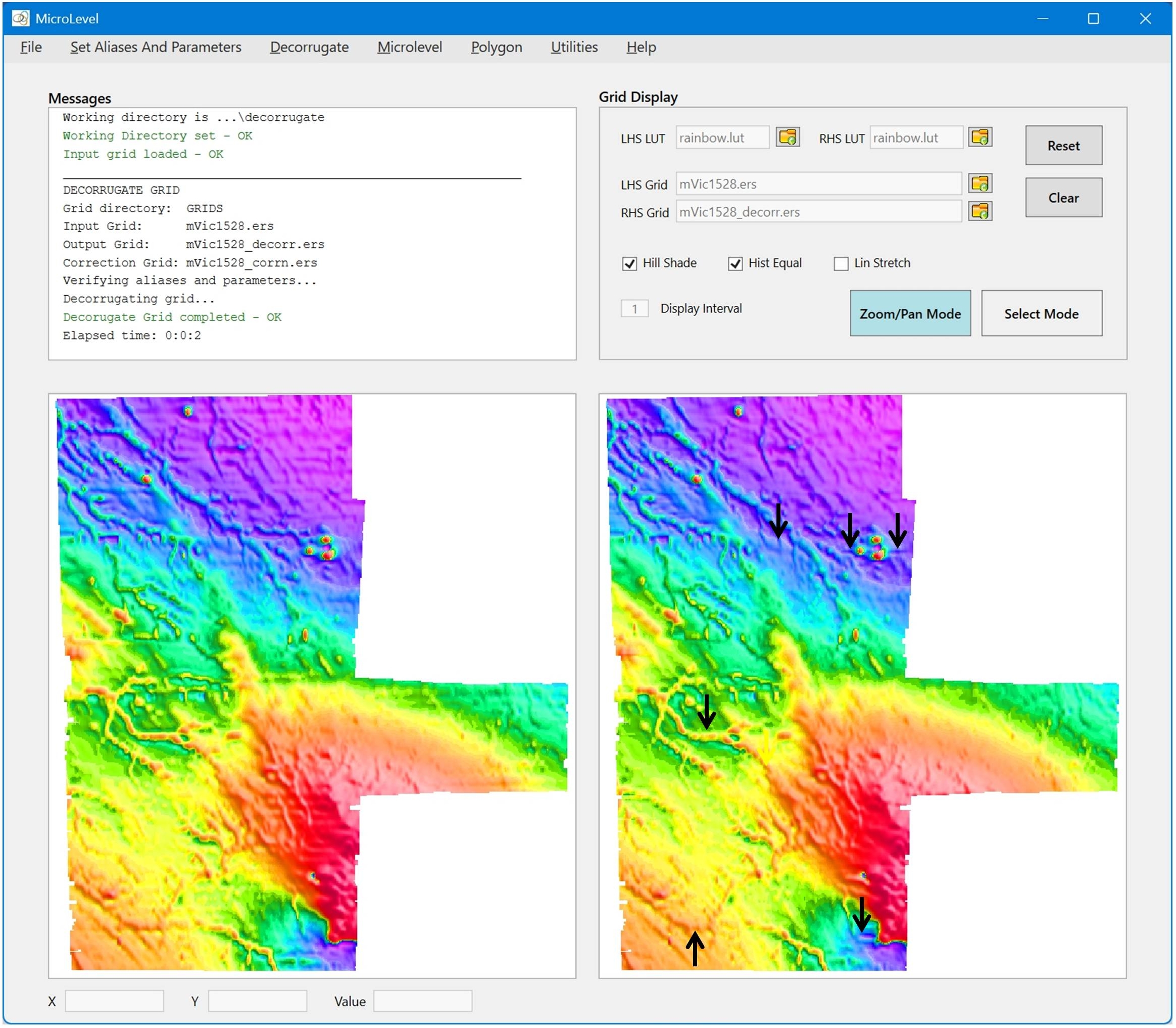
The black arrows on the figure indicate areas where the decorrugation has either removed real anomalies in the flight line direction, or introduced artefacts due to low-pass filter "leakage". We are now going to re-do the decorrugation, but this time use polygons to exclude some areas from the analysis. To digitise polygons - see Tutorial 3: Creating a polygon.
- Load Polygons – Polygons|LoadPolgons. Load the four polygon files for project 1528. You can select multiple files by using Ctrl+Click or Shift+Click in the normal way. The polygons will be plotted on top of the image in the left panel.
- Decorrugate the grid – Decorrugate|Decorrugate. This will launch the Decorrugate process using the loaded polygons, and current alias and parameter settings. Wait for the process to finish. The decorrugated grid will appear in the right panel, as shown in the figure below.

The grid has been satisfactorily decorrugated. Any number of polygons can be used to control decorrugation. However, the polygons are always "exclude" polygons - i.e. the areas inside the polygons are not decorrugated.